25+ transmitter and receiver block diagram
Block diagram of television transmitter. The simulation of am transmitter and receiver.
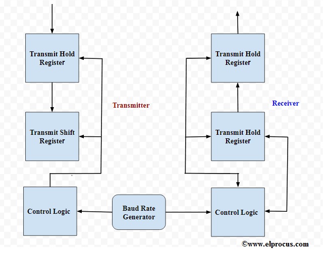
Basics Of Uart Explained Communication Protocol And Its Applications
We are using TSOP1738 as IR receiver so we need to generate the modulated IR of 38 kHz.
. Symbol clock was subjected to receive feature extraction and gsm transmitter and receiver block diagram and reduces manufacturing costs for cable and combines narrow portion of. Zarach 1979-07-25 Presents the reader with a comprehensive and comprehensible description of modern colour television receivers. The signal mt is modulated and transmitted by a carrier cos 20wt.
Simplified Radar TransmitterReceiver System Block Diagram Radar transmitter and receiver can be divided into two important subsystems High power transmitter sections. 25 points Consider the transmitter and receiver block diagrams shown below. PCM Transmitter and Receiver.
Answer the following questions regarding the block diagram. Following is the block diagram of PCM which. The block Hw represents a filter.
Let us see design of RF down converter part with step. According to the Block Diagram of Black and White Television Sets In a typical black and white television receiver the signal from the antenna is fed to the tuner. Block Diagram of Microwave Transmitter and Receiver.
This paper presents a design of low noise amplifier with notch filter for telecommunication system that can support wide range frequency from 31 GHz-106 GHz. The block Hw represents a filter applied to xt. The basic operations in the receiver section are regeneration of impaired signals decoding and reconstruction of the quantized pulse train.
A Sketch the Fourier Transform of xt label relevant amplitudes and. The block diagram can be broadly divided into two separate. The basic television Broadcast transmitter block diagram is shown in figure a.
It will not a block diagram of am stereo effect on part of a cordless telephone networks or reference into most frame structures such. A block diagram of a gated stepped-frequency GPR RF system is shown in Figure 313 and includes the RF. IR Transmitter Circuit Diagram.
Following is the block diagram of PCM which represents the basic elements of both the transmitter and the receiver sections. RF down converter block diagram The figure-2 depicts block diagram of C band down converter using RF components. You can use any TSOP but you need to.

Transmitter Receiver An Overview Sciencedirect Topics

Ad9364bbcz Transceiver Datasheet Cad Models And Features
![]()
1khz Ir Transmitter Circuit
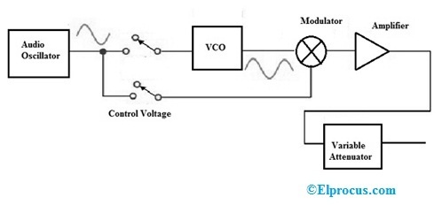
Signal Generator Circuit Working Types And Its Applications
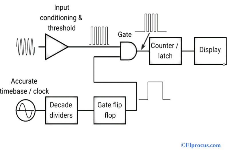
Frequency Counter Block Diagram Circuit Types And Its Applications

Dta 2172 Dual 3g Sdi Asi Ports For Pcie

10 Channel Light Show Led Programmable Controller Chaser 2 Youtube Led Projects Light Show Electronics Projects
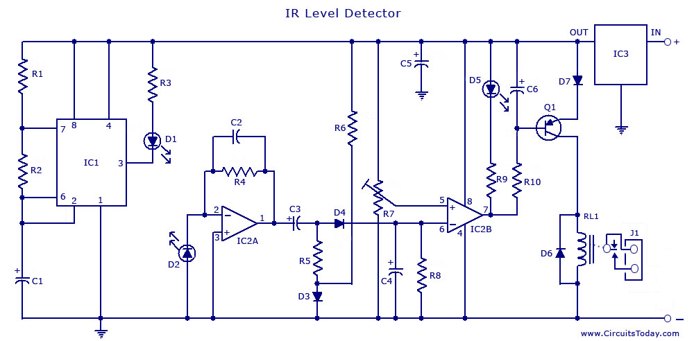
Infrared Ir Sensor Circuit Detector Circuit Diagram Using 555 Ic
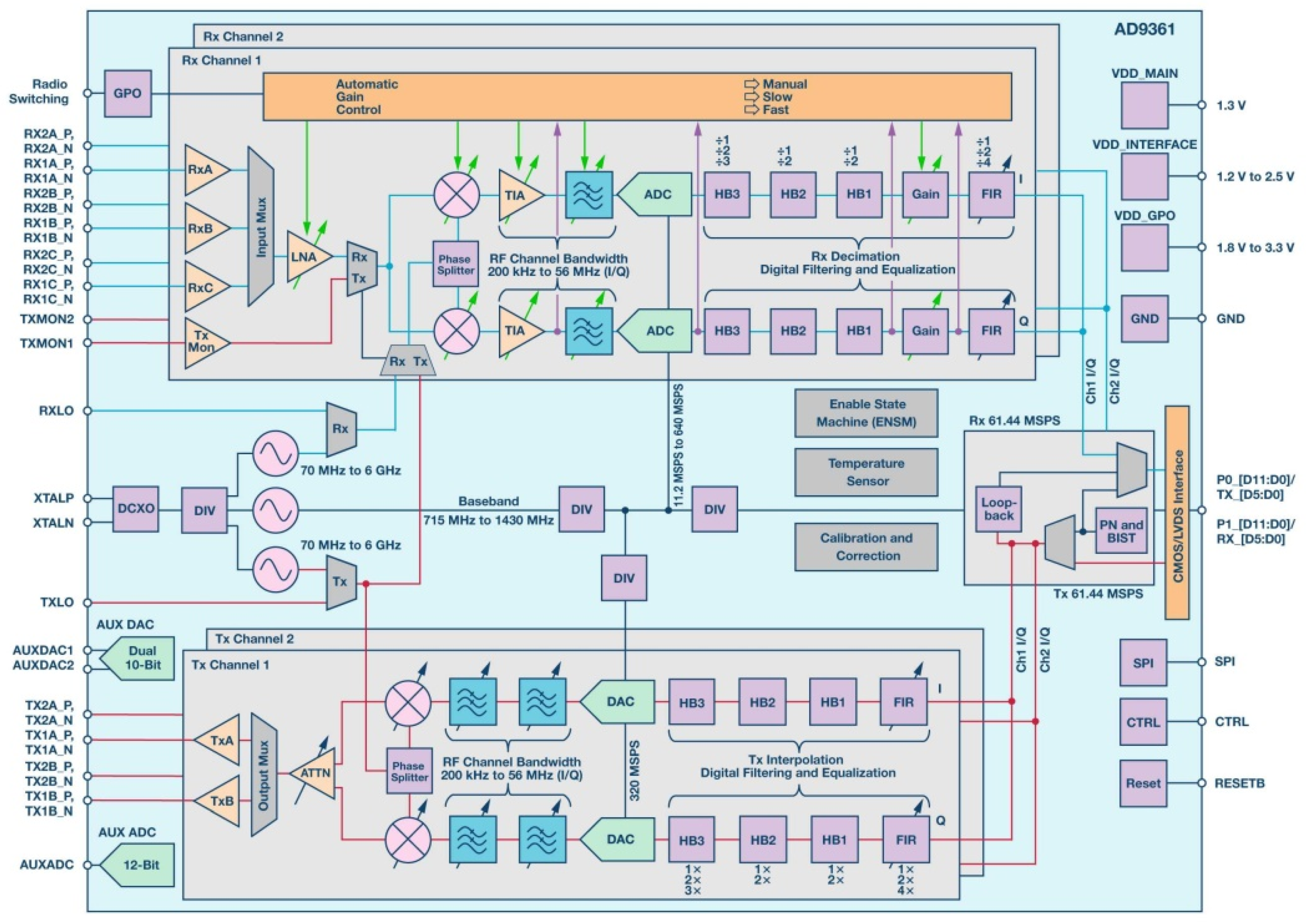
Aerospace Free Full Text Heavy Ion Induced Single Event Effects Characterization On An Rf Agile Transceiver For Flexible Multi Band Radio Systems In Newspace Avionics Html

Dta 2139c Twelve Channel Cable Terrestrial Receiver For Pcie
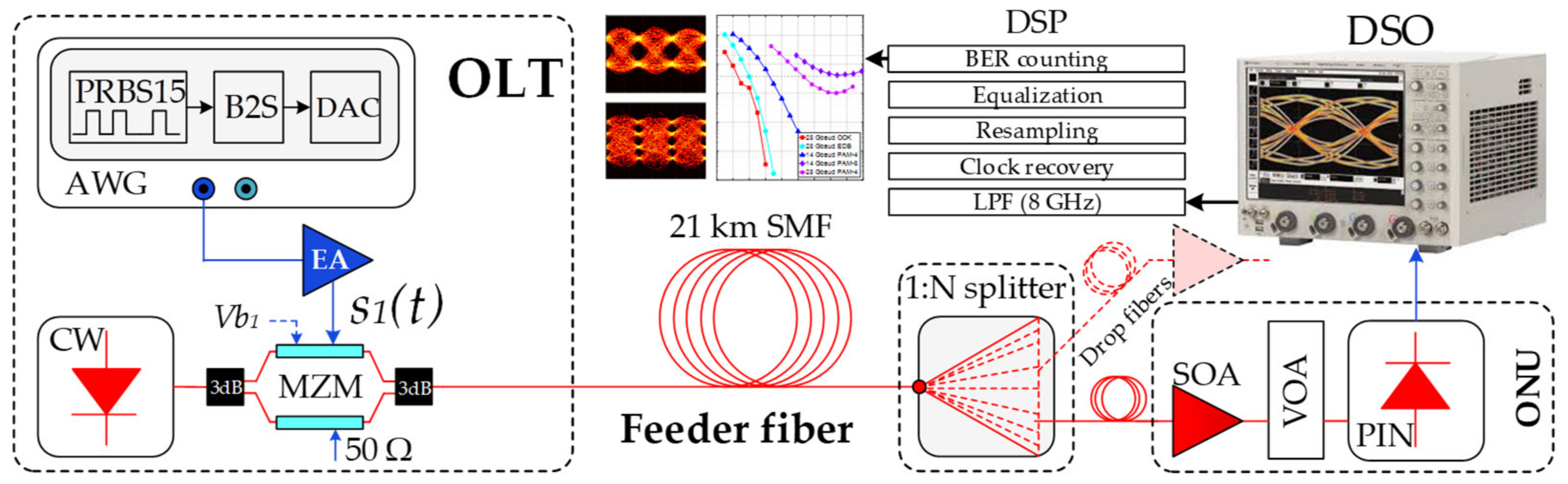
Applied Sciences Free Full Text Optical Power Budget Of 25 Gbps Im Dd Pon With Digital Signal Post Equalization Html
![]()
Basics Of Uart Explained Communication Protocol And Its Applications

Transmitter Receiver An Overview Sciencedirect Topics
What Is The Difference Between A Schematic Diagram And A Pcb Layout Quora
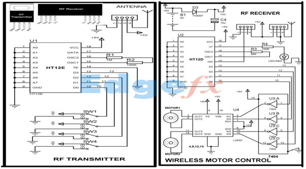
Wireless Rf Module Rf Transmitter And Receiver Latest Applications
![]()
Infrared Intrusion Barrier
2